Electric Pumps
COA, COP series
Immersible pumps

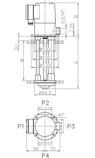
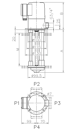
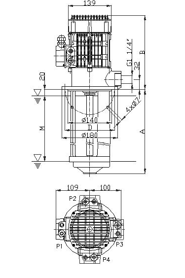
The electric pumps are equipped with a flange which enables their fitting directly on top of the tank, which contains the pumped liquid. The maximum and the minimum immersion level is shown on the dimensional drawing. The pumps must not be used for pumping of flammable or combustible liquids. The size of impurities in the pumped liquid should not exceed 0.5mm. Should larger impurities be found in the pumped liquid the pump suction opening should be equipped with a protective sieve.  The standard paint finish the electric pumps are supplied with is S 2003 synthetic primer.

COP Pumps = „Plastic execution“
COA Pumps = „Aluminium execution“

There is a table with all executions and their materials at the end of this page (section „Used materials“)!
 

HEAD 2-4m
FLOW 16-260l/min
Coa cop

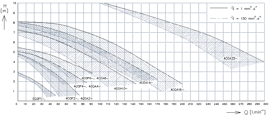
COA, COP Pumps - Technical Data

Type Head Pressure Flow Power Current Assured current
m kPa l/min kW A (by 400V) A (by 400V)
2COP1-; 2 20 16 0,05 0,14 0,22
4COP2-; 4COA2- 4 40 25 0,09 0,26 0,35
4COP4-; 4COA4- 4 40 40 0,12 0,33 0,45
4COP6-; 4COA6- 4 40 63 0,155 0,43 0,6
4COA10- 4 40 100 0,36 0,71 0,84
4COA14- 4 40 140 0,39 0,74 1,1
4COA16- 4 40 160 0,505 1,1 1,6
4COA25- 5 50 250 0,96 1,6 2,3

Characteristic of pumps COA, COP

COA, COP Pumps - Dimensions

Plastic pumps
Type A B M Kg
mm mm mm
2COP1-09 90 156 59 3,5
2COP1-10 100 156 69 3,5
2COP1-12 120 156 80 3,6
2COP1-14 140 156 100 3,6
2COP1-17 170 156 130 3,7
2COP1-22 220 156 180 3,8
2COP1-27 270 156 230 3,9
4COP2-09 90 156 59 3,5
4COP2-10 100 156 69 3,5
4COP2-12 120 156 80 3,6
4COP2-14 140 156 100 3,6
4COP2-17 170 156 130 3,7
4COP2-22 220 156 180 3,8
4COP2-27 270 156 230 3,9
4COP4-09 90 156 59 3,8
4COP4-10 100 156 69 3,8
4COP4-12 120 156 80 3,9
4COP4-14 140 156 100 3,9
4COP4-17 170 156 130 4
4COP4-22 220 156 180 4,1
4COP4-27 270 156 230 4,2
4COP6-09 90 171 59 4,5
4COP6-10 100 171 69 4,6
4COP6-12 120 171 80 4,6
4COP6-14 140 171 100 4,6
4COP6-17 170 171 130 4,7
4COP6-22 220 171 180 4,8
4COP6-27 270 171 230 4,9

Aluminium pumps
Type A B M Kg
mm mm mm
4COA2-09 90 156 59 3,4
4COA2-10 100 156 69 3,4
4COA2-12 120 156 80 3,5
4COA2-14 140 156 100 3,7
4COA2-17 170 156 130 3,8
4COA2-22 220 156 180 4,1
4COA2-27 270 156 230 4,4
4COA2-35* 350 156 310 4,9
4COA4-09 90 156 59 3,4
4COA4-10 100 156 69 3,5
4COA4-12 120 156 80 3,7
4COA4-14 140 156 100 3,8
4COA4-17 170 156 130 4
4COA4-22 220 156 180 4,4
4COA4-27 270 156 230 4,7
4COA4-35* 350 156 310 5,2
4COA6-09 90 171 59 4
4COA6-10 100 171 69 4,1
4COA6-12 120 171 80 4,3
4COA6-14 140 171 100 4,4
4COA6-17 170 171 130 4,6
4COA6-22 220 171 180 5
4COA6-27 270 171 230 5,3
4COA6-35* 350 171 310 5,8

Type A B M Kg
mm mm mm
4COA10-17 170 238 110 7,3
4COA10-20 200 238 140 7,4
4COA10-22 220 238 160 7,5
4COA10-27 270 238 210 7,6
4COA10-35 350 238 290 8,1
4COA14-17 170 238 110 7,7
4COA14-20 200 238 140 7,8
4COA14-22 220 238 160 7,9
4COA14-27 270 238 210 8
4COA14-35 350 238 290 8,5
4COA16-18 180 238 110 8,5
4COA16-21 210 238 140 8,7
4COA16-23 230 238 160 8,9
4COA16-28 280 238 210 9,2
4COA16-36 360 238 290 9,8
4COA25-18 180 246 90 9,3
4COA25-28 280 246 200 10,2
4COA25-36 360 246 280 10,9

Used material

POM = acetal copolymer; PA6 = polyamid
Type Impeller Chamber bottom Chamber Pump Tubes Shaft
2COP1- standard POM PA6+30% Glass PA6+30% Glass 1.0026 1.0060
HV execution POM PA6+30% Glass PA6+30% Glass stainless steel stainless steel
4COP2,4,6- standard POM PA6 PA6+30% Glass 1.0026 1.0060
HV execution POM PA6 PA6+30% Glass stainless steel stainless steel
4COA2,4,6- standard POM / Al Al alloy Al alloy 1.0026 1.0060
AV2 execution POM / Al Al alloy Al alloy CW508L stainless steel
AV execution Bronze Bronze Bronze Bronze stainless steel
4COA10 ,14- standard POM / Al Al alloy Al alloy 1.0026 1.0060
AV2 execution POM / Al Al alloy Al alloy Al alloy 1.4021
AV execution Bronze Bronze Bronze Bronze 1.4571
4COA16, 25- standard Al Al alloy Al alloy Al alloy 1.0060
AV2 execution Al Al alloy Al alloy Al alloy 1.4021
AV execution Bronze Bronze Bronze Bronze 1.4571

Spare parts

COP, CPP, COA2,4, 6
1. Pump body                                             10. Terminal box seal
2. Shaft with rotor                                      11. Terminal box
3. Stator complete                                     12. Terminal box lid seal
4. Impeller                                                    13. Termin box lid
5. Suction cover                                          14. Terminal block
6. Bottom bearing                                      15. Schield
7. Top bearing                                             16. Fan
8. Wavy washer                                          17. Fan cover
9. Splash ring